Editing Geometry |
  
|
Editing Geometry |
|
The WebOffice html client provides manifold edit functions that go beyond simple creating, editing and deleting objects. Also when creating or editing an object, the WebOffice html client offers the option to use construction tools which allow extreme accuracy. The following chapter is divided into several sections, use the links to quickly navigate through it.
oConstruction Tools for Creating Point Objects
oConstruction Tools for Creating Polyline or Polygon Objects
•Edit
•Copy
This action allows you to create new objects. If you want to create the object manually, simply click into the map and add vertices to set the geometry of your new object.
Note: It is possible to import the coordinate pairs of vertices within the Vertex Geometry button.

Create a polygon manually
While creating any type of object you can edit any vertex by right-clicking on the vertex. A context menu will open which provides several functions.

Vertex context menu
Icon |
Menu Item |
Description |
|
Add vertex |
Creates a line segment to the currently selected vertex. Note: This button is only available for polylines. |
|
Insert before |
A vertex will be placed (exactly in the center) between the last and the active vertex. |
|
Insert after |
A vertex will be placed (exactly in the center) between the active and the next vertex. |
|
Delete vertex |
Deletes the currently selected vertex. |
|
Move vertex by construction |
With this function it is possible to manipulate the position of an object's vertices by using construction tools. Note: See section Construction Tools for Creating Point Objects for detailed description. |
|
Add vertex by construction |
With this function it is possible a line segment may be added using the construction tools. Note: See section Construction Tools for Creating Point Objects for detailed description. |
|
Move feature |
Allows the repositioning of an entire feature, i.e. the entire geometry of a feature will be moved not only one single vertex. Both the direction and the distance to which the feature is being moved will be displayed dynamically as a line between current and desired position. |
Vertex context menu
It is also possible to just move a single vertex instead of the entire feature. Therefore, move the mouse pointer over a vertex then click and hold left mouse button. Move the mouse pointer to the new position and release the left mouse button. The vertex will be moved to the new position.
If the mouse pointer is moved during creating or moving vertices over an existing connecting line between two vertices it is possible to place a vertex directly on the connecting line. This behavior will be indicated by a change of the appearance of the mouse pointer.
While creating a polyline or a polygon object you can also right-click on the line to open an additional context menu.

Line context menu
Icon |
Menu Item |
Description |
|
Set as active line segment |
Defines the selected line segment as the active line segment Note: This button is only available for polygons. |
|
Insert vertex |
Inserts a new vertex at the current position of the line segment. This vertex can be replaced subsequently. |
|
Insert vertex by construction |
If you choose the menu item Insert vertex by construction then a set of construction tools is available for exactly inserting or moving a vertex. Note: See section Construction Tools for Creating Point Objects for detailed description. |
Line context menu
Construction Tools for Creating Point Objects
Instead of setting vertices manually the user can also use construction tools to create objects with accurate measures. See the following list explaining the construction tools available for point creation.

Construction tools for creating point objects
Icon |
Menu Item |
Description |
|
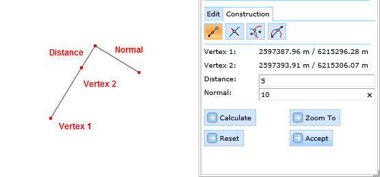
Construction by Alignment |
Tool for constructing by alignment using distance and orthogonal distance from a baseline.
|
|
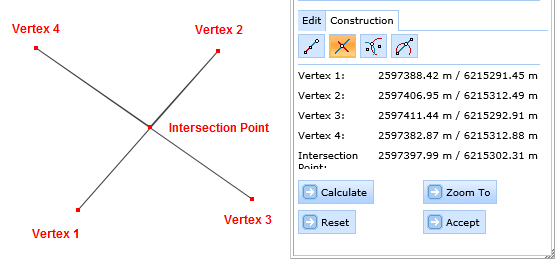
Intersection of two Lines |
Tool for constructing points by intersecting two base lines.
|
|
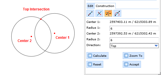
Circular Intersection |
Tool for constructing a point using circular intersection.
|
|
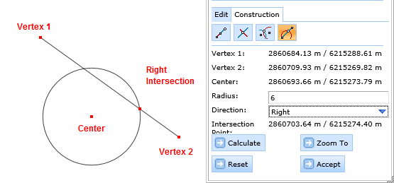
Intersection of line and circle |
This tool allows the determination of an intersection between a line and a circle. First you draw a baseline by setting two vertices. After drawing a circle (setting the center and the radius), the intersection of line and circle can be calculated (button 'Calculate').
Note: Since the intersection of base line and circle provides two intercept points, the function "Direction" (Right/Left) affords the opportunity to choose between these two intercept points. |
Construction tools for creating point objects
Construction Tools for Creating Polyline or Polygon Objects
When creating polylines or polygons different construction tools are available.

Construction tools for creating polyline or polygon objects
Icon |
Menu Item |
Description |
|
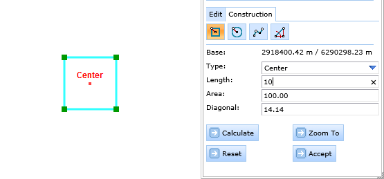
Generate Square |
Tool for constructing a square polygon.
|
|
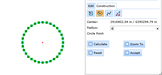
Generate Circle |
Tool for constructing an approximated circle polygon
|
|
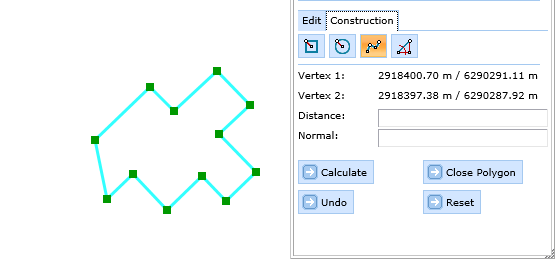
Orthogonal construction |
Tool for creating orthogonal polygons – used for supporting digitizing e.g. building outlines from aerial images.
|
|
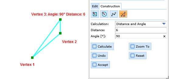
Construction by distance and/or angle |
Construct points using a base point and X/Y distance or distance and angle.
|
Construction tools for creating polyline or polygon objects
This edit action allows editing of features that already exist. Select an object in the map by clicking on it or selecting it by rectangle. If a selection returns more than one object the user will get a list and will have to choose just one of them by a click at the button at the beginning of the line.

Selecting one object for editing
Change the geometry by either adding additional vertices or edit existing vertices via Context Menu.
Note: It is also possible to import the coordinate pairs of vertices within the Vertex Geometry button.

Editing an existing object
With this edit action you can copy existing objects. Select an object to copy in the map by clicking on it or selecting it by rectangle. If your selection returns more than one object you will get a list and you'll have to choose just one of them by a click at the button at the beginning of the line. If necessary select the new position of the object by a mouse click at the map.

Copy an existing object
This action allows you to delete existing objects. Select an object to delete in the map by clicking on it or selecting it by rectangle. If your selection returns more than one object you'll get a list and you'll have to choose just one of them by a click at the button at the beginning of the line. After a click at the Submit editing button the object get deleted from database. If the delete operation was successful the attribute form is replaced by a report of success and the object won't be displayed in the map any longer.

Delete an existing object
With this tool you can split an existing object. Select an object to split in the map by clicking on it or selecting it by rectangle. In addition the object will be labeled as selected. Draw a parting line, which intersects the selected object by at least two vertices. After a click at the Submit editing button the object will be split along the parting line.
Note: It is not allowed that the parting line crosses the object once, or else the split action cannot be performed and fails with an appropriate notice.
Note: After the split action both objects hold the same attribute values as the original object.

Split an existing object
With this tool you can merge two existing objects. Select the object from which you want to take over the attribute data, first. The object gets selected in the map. Select the second object to be merged with the first one. The object gets selected in the map. The shape of the merged object gets displayed as well. Click on Submit editing button in the edit tool form to save the object.

Merge two existing objects
Note: See chapter Editing for details about the tool configuration in WebOffice author.
Note: See chapter Edit Layers for details about configuration of edit layers in WebOffice author.