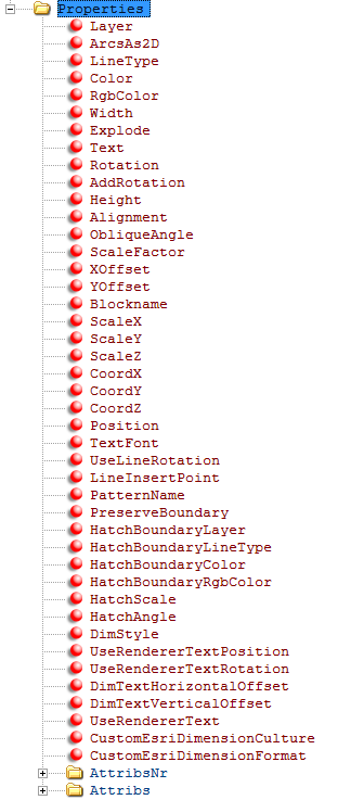
Properties

The folder Properties is a subfolder of the folder DxfEntity. The properties include the definition of each entity (layer, color, etc.). Which attribute is used for which DXF Entity is described in the Properties column.
Property |
Description |
mandatory |
optional |
||
Layer |
Layer for the entity in CAD. If no value is entered, the object is placed on the layer 0. Concerns each DxfEntity.
|
|
x |
||
ArcsAs2D |
POLYLINE attribute. Arches are exported as 2D arches. If not active (0), GIS 3D arches are exported as CAD 3D lines. Value can be 0 or 1. Default = 1. |
|
x |
||
LineType |
Line type of the entity. Concerns each DxfEntity. |
|
x |
||
Color |
Color of the entity. Concerns each DxfEntity. |
|
x |
||
RgbColor |
Default attribute instead of color. Concerns each entity. RGB values separated with comma, e.g. 255,10,23 |
|
x |
||
Width |
Width of the polyline for the entity type POLYLINE. |
|
x |
||
Explode |
POLYLINE attribute: Splits a polyline in the individual line segments. Values: 0 or 1 |
|
x |
||
Text |
Text value for TEXT in case of entity type TEXT. |
|
x |
||
Rotation |
Rotation in Alt degree for TEXT or INSERT. |
|
x |
||
AddRotation |
Addend for attribute rotation for TEXT or INSERT. |
|
x |
||
Height |
Text height for entity type TEXT. |
|
x |
||
Alignment |
Alignment (for entity type TEXT) Middle,Center,Left,Right,Bottom(Center,Left,Right),Middle(Center,Left,Right),Top(Center,Left,Right) |
|
x |
||
ObliqueAngle |
Inclination angle for entity type TEXT. Condition: Value greater than -85 and less than 85 |
|
x |
||
ScaleFactor |
Width factor for entity type TEXT. |
|
x |
||
XOffset |
TEXT attribute: X offset |
|
x |
||
YOffset |
TEXT attribute: Y offset |
|
x |
||
Block Name |
for entity type INSERT – block name in CAD |
|
x |
||
ScaleX |
X scaling for entity type INSERT. |
|
x |
||
ScaleY |
Y scaling for entity type INSERT. |
|
x |
||
ScaleZ |
Z scaling for entity type INSERT. |
|
x |
||
CoordX |
X coordinate of the insert point for entity type INSERT. |
|
x |
||
CoordY |
Y coordinate of the insert point for entity type INSERT. |
|
x |
||
CoordZ |
Z coordinate of the insert point for entity type INSERT. |
|
|
||
Position |
Insert position for entity type INSERT. Values: Mid (corresponds to middle/middle), Ins (corresponds to insert point) Default = INS |
|
x |
||
TextFont |
TEXT attribute: Font name |
|
x |
||
UseLineRotation |
TEXT attribute: Is used as rotation angle of the line at the place of the insert point. Value can be 0 or 1. Default = 1 |
|
x |
||
LineInsertPoint |
TEXT attribute: Insert point of the text on the line: Start,Mid,End. Default = Mid |
|
x |
||
PatternName |
HATCH attribute: hatch name. Default = _SOLID |
|
x |
||
PreserveBoundary |
HATCH attribute: Boundary line preserved. Value can be 0 or 1. Default = 1 |
|
x |
||
HatchBoundaryLayer |
HATCH attribute: Layer for boundary line of the hatch. |
|
x |
||
HatchBoundaryLineType |
HATCH attribute: Line type for boundary line of the hatch. |
|
x |
||
HatchBoundaryColor |
HATCH attribute: Color for boundary line of the hatch. |
|
x |
||
HatchBoundaryRgbColor |
HATCH attribute: RGB color for boundary line of the hatch. |
|
x |
||
HatchScale |
HATCH attribute: Hatch scaling factor. Default = 1.0 |
|
x |
||
HatchAngle |
HATCH attribute: Hatch angle. Default = 0.0 |
|
x |
||
DimStyle |
The dimension style for the dimensions. The dimension style is defined in the CAD header file. If not defined, the default is used. |
|
x |
||
UseRendererTextPosition |
DIMENSION attribute: If 1, the position of the dimension text is used by the renderer. Default = 0. |
|
x |
||
UseRendererTextRotation |
DIMENSION attribute: If 1, the rotation of the dimension text is used by the renderer. Default = 0. |
|
x |
||
DimTextHorizontalOffset |
DIMENSION attribute: Horizontal offset. Default = 0. |
|
x |
||
DimTextVerticalOffset |
DIMENSION attribute: Vertical offset. Default = 0. |
|
x |
||
UseRendererText |
DIMENSION attribute: Default = 0. If this attribute exists and has the value of 1, the customs dimension texts are exported instead of the real dimension texts. |
|
x |
||
CustomEsriDimensionCulture |
DIMENSION attribute: Default = CurrentCulture. The ESRI custom dimension texts are from the datatype double. For AutoCAD the data type need to be converted into the data type string. The CustomEsriDimensionCulture attribute specifies the culture, which is used for the conversion. E.g.: In Austria a comma is used for a decimal point. In the US a point is the typical format. Format: xx-xx Examples: •en-US > for USA •de-AT > for Austria •de-DE > Germany |
|
x |
||
CustomEsriDimensionFormat |
DIMENSION attribute: Default = G. The ESRI custom dimension texts are from the datatype double. For AutoCAD the data type need to be converted into the data type string. The CustomEsriDimensionFormat specifies the numeric format. Examples: E, F, G, N
|
|
x |
||
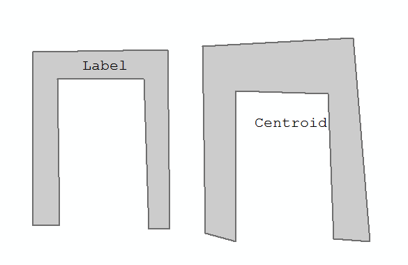
PolygonInsertPoint |
TEXT attribute: For the placement of polygon labels. Allowed values = Label (default), Centroid. The value Label positions the text as center point of the polygon. The position depends on the polygons geometry, but is always located inside the polygon. The value Centroid positions the text as centroid, which can also be located outside the polygon.
|
|
x |
||
LinetypeScale |
POLYLINE attribute. All entities for the task get the configured LTScale. The here definied value overrules the LinetypeScale from the General section. The value must be greater than 0. |
|
x |
||
MinNrOfPartsPerBezierSegment |
POLYLINE and HATCH attribute for Bezier curves. Determines the minimum amount of parts per Bezier or eliptic arc segment. Each segment is splitted into a certain amount of parts. Default value is 10. |
|
x |
||
MaxAngleDeviationGrad |
POLYLINE and HATCH attribute for Bezier curves. Determines the maximum angular deviation between the segments. If the angle is exceeded, the distance to the next vertex is halved as long as the angle is not exceeded anymore. Thereby, the amount of parts in one segment is increased. The maximum for the bisection per segment is 10. The default value is 5. |
|
x |